Ryobi BTS15 Operator's Manual
Browse online or download Operator's Manual for Power tools Ryobi BTS15. Ryobi BTS15 Operator`s manual User Manual
- Page / 38
- Table of contents
- BOOKMARKS
- OPERATOR'S MANUAL 1
- 10 in. (254 mm) TABLE SAW 1
- TABLE OF CONTENTS 2
- RULES FOR SAFE OPERATION 3
- ELECTRICAL 7
- GLOSSARY OF TERMS 8
- UNPACKING 9
- TOOLS NEEDED 9
- LOOSE PARTS LIST 10
- LOOSE PARTS LIST 11
- FEATURES 12
- ° and 45° 13
- ASSEMBLING LEG STAND 15
- ASSEMBLING STORAGE BRACKETS 15
- ASSEMBLY 16
- OPERATION 19
- TYPES OF CUTS 21
- WARNING: 21
- RIP FENCE 25
- ADJUSTMENTS 28
- To Adjust the Miter Table 34
- MAINTENANCE 36
- TROUBLE SHOOTING 37
- 10 in. (254 mm) Table Saw 38
Summary of Contents
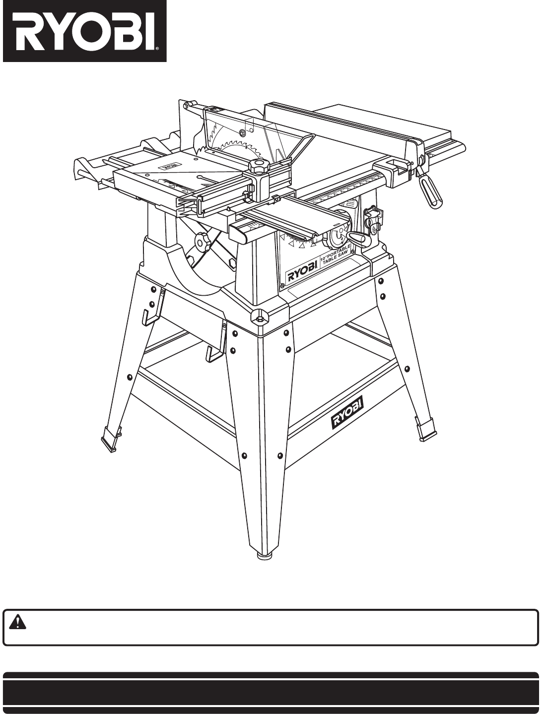
OPERATOR'S MANUAL10 in. (254 mm) TABLE SAWBTS15SAVE THIS MANUAL FOR FUTURE REFERENCEYour new Table Saw has been engineered and manufactured to Ry
Page 10Fig. 2KeyNo. Description Qty.1 Miter Fence ...
Page 11The following items are included with your table saw leg stand.LOOSE PARTS LISTFig. 3A. Storage Bracket ...
Page 12GETTING TO KNOW YOUR SAWYour saw is designed to perform as a versatile, accurate,precision cutting tool that is easy to operate.It is equipped
Page 13Fig. 5SWITCHKEYFEATURESWARNING:Although some of the illustrations in this manual areshown with the blade guard removed for clarity, do notopera
Page 14BLADESIt is recommended that you use a RYOBI 10 in. (254 mm) Combination Blade, which is provided with the BTS15 Table Saw.You will get maximum
Page 15ASSEMBLYFig. 7Fig. 8Assembly is best done in the area where the saw will beused. When you remove the table saw base, loose parts, andhardware f
Page 16ASSEMBLYTO MOUNT THE TABLE SAW TO THE LEGSTANDSee Figure 9. Take the following from a small hardware bag:4 hex bolts (5/16-18 x 2 in.)4 hex nu
Page 17TO INSTALL RIP FENCESee Figure 11.To install the rip fence, place the rear lip on the rear rail andpull slightly toward the front of the unit.
Page 18BLADE AND GUARD ASSEMBLYWARNING:Do not connect to power supply until assembly is complete.Failure to comply could result in accidental starting
Page 19OPERATIONFig. 17PUSH BLOCKSPUSH STICKS Use the right type of blade for the cut being made. Use the blade guard assembly for all through cuts.
Page 2 Rules for Safe Operation ... 3-6 Electrical ...
Page 20OPERATIONFEATHERBOARDA featherboard is a device used to help control the workpieceby guiding it securely against the table or fence. Featherboa
Page 21OPERATIONFig. 20Bevel Rip CutRip CutCross CutMiter CutCompound (Bevel) Miter CutBevel Cross Cut1 The kerf (the cut made by the blade in the wo
Page 222789101112131415001GULLETFig. 22FRONT RAILFig. 20BEVELINDICATORBEVELLOCKING LEVERBEVELHANDLEFig. 21LOCKINGHANDLEBLADERIPFENCE2 IN.MARKSCALESCAL
Page 23OPERATIONFig. 24TO USE OUTFEED SUPPORTSee Figure 24.The outfeed support slides to give the operator additionalsupport for cutting long workpiec
Page 24OPERATION Set the miter fence to 0˚ and tighten the lock knob. Place a support (the same height as saw table) behind thesaw for the cut work.
Page 25OPERATIONTO MAKE A BEVEL CROSS CUTSee Figure 30.It is recommended that you place the piece to be saved onthe left side of the blade and that yo
Page 26OPERATIONTO MAKE A COMPOUND MITER CUTIt is recommended that you place the piece to be saved onthe left side of the blade and that you make a te
Page 27OPERATIONWARNING:Never feed wood with your hands when making any non-through cut such as rabbets or dadoes.WARNING:When making a non-through c
Page 28ADJUSTMENTSREMOVING/REPLACING THE THROAT PLATESee Figure 33.WARNING:Make sure the switch is off and the plug is out of the outlet.Failure to do
Page 29ADJUSTMENTS45º Adjustment0º AdjustmentFig. 36TO REMOVE THE BLADESee Figures 35 - 37.Use the two wrenches supplied with the saw in this proce-du
Page 3IMPORTANTServicing requires extreme care and knowledge and shouldbe performed only by a qualified service technician. Forservice we suggest you
Page 30ADJUSTMENTSALIGNING SPREADER WITH THE BLADESee Figures 38 - 39.WARNING:Failure to turn the table saw off, remove the switch key,and unplug the
Page 31ADJUSTMENTSWARNING:Before performing any adjustment, make sure the tool isunplugged from the power supply and the switch is in theoff ( )
Page 32ADJUSTMENTSTO AJUST THE SLIDING MITER TABLE ASSEMBLYThe sliding miter table assembly has been preset at the factory to be parallel to the blade
Page 33ADJUSTMENTSCHECKING SLIDING MITER TABLE ASSEMBLYTo Check Miter Base Parallelism:WARNING:Begin by unplugging your saw. Failure to unplug sawcoul
Page 34ADJUSTMENTSLTo Check Miter Fence AlignmentSee Figure 43.The miter fence must be perpendicular to the blade when setat zero degrees.WARNING:Begi
Page 35ADJUSTMENTSWARNING:Begin by unplugging your saw. Failure to unplug sawcould result in accidental starting causing possible seriousinjury.TO ADJ
Page 36GENERAL MAINTENANCEWARNING:Always begin by disconnecting the power supply. Periodically check all clamps, nuts, bolts, screws, andbelts for ti
Page 371. Blade is out of balance.2. Blade is warped or damaged.3. Saw is not mounted securely to alevel work surface.1. Rip fence not mounted correct
Page 38983000-290 11-04RYOBI TECHNOLOGIES, INC.1428 Pearman Dairy Road Anderson, SC 29625Post Office Box 1207 Anderson SC 29622-1207Phone 1-800-525-
Page 4Safe operation of this power tool requires that you read andunderstand this operator's manual and all labels affixed tothe tool. Safety is
Page 5 BLADES COAST AFTER TURN OFF. NEVER USE IN AN EXPLOSIVE ATMOSPHERE. Normalsparking of the motor could ignite fumes. INSPECT TOOL
Page 6 CHECK WITH A QUALIFIED ELECTRICIAN or servicepersonnel if the grounding instructions are not completelyunderstood or if in doubt as to whe
Page 7ELECTRICALEXTENSION CORDSWhen using a power tool at a considerable distance from apower source, be sure to use an extension cord that has thecap
Page 8Anti-Kickback Pawls (Fingers)Device which, when properly installed and maintained, isdesigned to stop the workpiece from being kicked backtoward
Page 9The saw is factory set for accurate cutting. After assem-bling it, check for accuracy. If shipping has influenced thesettings, refer to specifi
Related products and manuals for Power tools Ryobi BTS15
 (16 pages)
(12 pages)
(22 pages)
(16 pages)
(16 pages)
(12 pages)
(22 pages)
 (25 pages)
(20 pages)
(14 pages)
(16 pages)
(12 pages)
(18 pages)
(10 pages)
(22 pages)
(30 pages)
(22 pages)
(14 pages)
(17 pages)
(23 pages)
(16 pages)
(25 pages)
(20 pages)
(14 pages)
(16 pages)
(12 pages)
(18 pages)
(10 pages)
(22 pages)
(30 pages)
(22 pages)
(14 pages)
(17 pages)
(23 pages)
(16 pages)
© 2020, manymanuals.com. All rights reserved. | 0.083 s |
 Manymanuals.com
 Manymanuals.de
 Manymanuals.fr
 Manymanuals.it
 Manymanuals.pl
 Manymanuals.cz
 Manymanuals.es
 Manymanuals-pt.com
Comments to this Manuals